Introduction
An optical table, or bench, is the optical equivalent of the very popular solderless prototyping breadboards that many electronics hobbyists regularly use to test and develop their electronic circuits. In fact the optical table has sometimes been referred to as an optical breadboard, although optical table or bench are the more conventional terms.
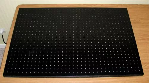
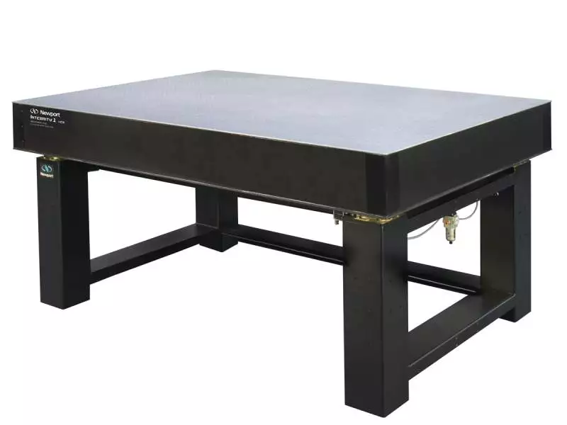
But that is where the similarity abruptly ends since there is a huge difference in physical size between these so-called “boards”. Whereas an electronic breadboard is often a small strip of plastic with a matrix of electrical contacts that is typically about 17cm x 5cm and is designed to hold small resistors, capacitors, ICs and other electronic components, the optical breadboard or table can be 2-3 metres long and the same again in width as the comparison below shows:
This is because the purpose of an optical breadboard (and from now on I will refer to them as optical tables or benches) is designed securely to fix the various optical components such as lenses, mirrors, diffraction gratings, lasers, etc. for an experiment. All these optical elements require their own supports, rails and stands and so the final size of the table needed to accommodate all these components becomes significantly larger.
The final objective, nevertheless, remains the same: to set up a certain optical physics or chemistry experiment with securely attached components in order to help achieve an experiment’s objectives.
Commercially available optical tables are extremely expensive and the price increases dramatically with their size. Even a relatively small table, say 60 cm x 40 cm, can cost several hundred dollars and the larger ones are well beyond the budgets of most home experimenters, who in any case will have more important equipment to spend their money on.
When you consider that these benches are really only large sheets of aluminium that have a matrix of equally spaced, drilled and tapped holes over the surface, plus some dampening mechanism in the table legs designed to reduce vibrations, I am always slightly amazed at their very high cost!
I suppose that for professional experiments requiring an extremely high degree of stability this cost is justified. However, since we amateur experimenters are not about to detect cosmological gravitational waves passing through the earth or some similar highly subtle physical phenomenon, we need something simpler and cost-effective.
So this post describes the construction of a simple optical bench that I came up with some time ago that can be made by the home experimenter at reasonable cost.
Materials
The following is for the construction of a 3 ft x 2 ft (0.9 m x 0.6 m) table. These dimensions are compact enough to fit easily on a writing desk or kitchen table, but large enough to accommodate a number of components for designing spectrometers, and for experiments in optical interference, fibre optics and so on.
You will need the following materials:
A sheet of chipboard or MDF (Medium Density Fibreboard) 3ft by 2ft by 0.75 inch thick. MDF should be your first choice since the chipboard tends to splinter when being drilled. Plywood is another good alternative. The thickness of ¾-inch is a good compromise between weight and stiffness, ½ inch being a little too thin for a bench of these dimensions.
A piece of acrylic sheet 5/16” (8 mm) thick, of the same size as the wood board (trade names are Plexiglas, Lexan or Perspex). Acrylic plastic sheet is very strong for its weight, and is easier to work with than metal. If the 5/16” thickness is unavailable, ¼” will work fine.
Metal sheet of the same dimensions to go on top of the acrylic sheet (this is optional).
Some standard DIY tools – electric hand-drill and bits, carpenter’s set square, centre punch, ¼”-20 tap (or metric equivalent) for threading the holes.
Contact adhesive, spray paint or lacquer, rubber feet.
Assembly
Cut the wood base to size ensuring that the edges are square, and sand the edges and both sides.
Cut the acrylic sheet to size (or preferably have it done at the time of purchase). When purchased, the acrylic plastic will be supplied with two protective peel-off paper sheets that should not be removed until ready to use. The acrylic surface will be glossy, and the side to be bonded will require a good sanding with medium then fine abrasive paper so as to form a good bond with the base.
Using a paintbrush, apply a thin layer of contact adhesive (Bostik™ or similar) to both the wood and plastic sheet then carefully place the two pieces together making sure they are precisely aligned. Contact adhesive forms an immediate bond with very little play so there is no room for error. If you misalign the parts they will be very difficult to separate afterwards. Practice first on gluing together two small pieces and check the amount of play and adjustment you can make.
With my design I wanted to add a metal top to the table. The main choices were steel, aluminium or sheet metal. Steel and sheet metal are the cheapest options, but aluminium is easier to work with and drill. In end in I chose aluminium, and was able to obtain some 12-gauge aluminium printing plates. These have a dull, grained and anodised upper surface and a shinier un-grained back surface. Unfortunately, 12-gauge printing plates are too thin to be used alone. To achieve a thicker sheet I glued three identical plates together with contact adhesive to give 36-gauge and when dry, this laminate was glued to the acrylic sheet (see schematic below).

Drilling the Holes
With the aid of a large carpenter’s set-square, a matrix of lines was drawn out at 1-inch intervals across the whole table. If you prefer you can make holes with ½ inch centres, but this means you will have to drill four times as many holes. For a 3ft by 2ft table, with 1-inch centres, and allowing for a 1-inch border, a total of 805 holes need to be drilled! With a centre punch carefully mark all positions for drilling. This takes time! Care, attention and patience at this stage are paramount since this will determine the final precision of your optical table!
The size and the thread of hole I chose for my table was ¼ -20 Imperial. This was because I have in my optical component collection several second-hand lens holders, supports and other fixtures with this size and thread. Metric sizes and threads are of course just as effective.
Clearly, it is most important to maintain the hand-drill vertical at all times to ensure the final support and optical component will be perpendicular to the table. It is difficult to use a drill stand in this situation. Although a drill mount would maintain the drill bit vertical, the sheer size of the table required and the frequent changes in position that are necessary negate this possibility. The alternative is to have the drilling carried out at a professional metal working shop on a jig, but this adds to the cost.
With care and attention, most if not all of the holes can be successfully drilled vertically by hand and the drill depth required is only several millimetres.
The most time-consuming and laborious stage comes next – tapping all the holes! Again, patience and attention to detail are very important. Take several breaks during this process.
Make sure that you use a pre-tap followed by the final tap to achieve a good secure thread for each and every hole. All the holes should be drilled and tapped to a minimum depth of about half an inch (12mm). This is sufficient to hold optical components securely in place with the fasteners which are usually hex-head screws or bolts. They have to penetrate through the top sheet (if used), the acrylic layer and the wooden baseboard of the table.
Finishing
The fully drilled and tapped table was undercoated with spray paint, followed by a minimum of 2 coats of semi-matt black paint, again best applied from a spray can or airbrush. I added an additional spray-coat of semi-matt acrylic lacquer to improve abrasion resistance. For vibration isolation, 4 Sorbothane™ anti-vibration feet were attached to the corners of the table to absorb and dampen unwanted vibrations.
Here are two images of my completed optical table in action with an experimental setup for a Littrow mounted spectrometer…
Conclusions and Afterthoughts...
This table has served me well for several years experimenting with optical equipment and spectrometer designs, as several pictures elsewhere on this site will testify.
However, if I were to construct a second table, there is at least one change I would make. With time, I have noticed some delamination of the top aluminium sheet around the holes. This was due to my use of multiple layers (aluminium printing plates) to increase the thickness of the top metal sheet. With the frequent screwing and un-screwing of components, areas around some of the holes began to delaminate and produce small raised domes with poorer stability.
If you are able to find, and can afford, a thicker sheet (at least 1/8″ or 3/16″), this would be ideal. Otherwise, using the acrylic sheet as the final top layer with no metal top might be a better solution.
Good luck with your own design !


Pingback: Spectrometer Designs -
Pingback: Three Simple "Demo" Spectrometers -