The development of the spectroscope over the last 160 years since its invention has paralleled the evolution in technological advances. This is particularly the case for the last several decades as the development of more efficient electronic detectors have gradually replaced the photographic film. Much progress has been made in this area of detection. But it is equally fascinating to examine the technical considerations and design changes made to the actual internal arrangement of the main optical elements inside a spectrometer that have been tried, modified and evaluated over the years. These internal changes have all been made in attempts to improve the optical and spectral performance for various experiments, many of them highly specialized applications in the fields of physics, chemistry and astronomy. But before we start, a quick word on the names…
Spectrometer, Spectrograph or Spectroscope?
The terms spectrometer, spectrograph and spectroscope are used interchangeably these days, with the most popular name being spectrometer. Basically they all refer to the same device. In this post, however, we will tend to be more specific because we shall be discussing their historical development.
Strictly speaking, a spectroscope splits up light which is subsequently detected visually by the eye, in a similar way to the telescope and microscope that still do this task today in many instances.
The term spectrograph used to be employed when the detector of choice 50 years ago was the photographic plate or film. This of course has now been replaced by far more sensitive charge coupled devices (CCD’s) and other solid-state sensors.
Finally, the term spectrometer was used when the best measuring device at the time was some form of amp or voltmeter whose needle moved when a signal was detected electrically. This output signal was then designed to be proportional to current or voltage in some way.
The term spectrometer is in widespread use today and has become more or less standardized, although the use of an actual “meter” was replaced many years ago by solid state detectors and powerful computer software.
The Classical Spectroscope
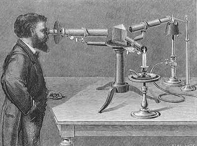
The very first so called “classical” spectroscope was constructed by its co-inventors Gustav Kirchhoff and Robert Bunsen in 1859. They subsequently went on to discover the elements caesium and rubidium with this instrument the following year. A simple schematic diagram of a basic prism spectroscope is shown in Figure 1 on the left, with the real item on the right:
Fig. 1 The Classical Kirchhoff-Bunsen Spectroscope
The classical spectroscope consists of 4 essential components: (1) an optical element used to produce a parallel (collimated) beam of light, (2) a dispersing element to separate the individual wavelengths of light, (3) a focusing element to collect the dispersed wavelengths of light and (4) some form of detector to record the signal.
In Fig.1 a light source L is focused onto the jaws of a narrow entrance slit S1 by lens L0. S1 is located in the focal plane of collimator lens L1. The parallel beam from L1 passes through the prism where it is deviated (refracted) by some angle θ(λ) depending on the wavelength λ. The focusing lens L2 forms an image S2(λ) of the entrance slit S1. The position l(λ) of this image along the imaging plane B is therefore a function of the wavelength, and multiple images S2(λ1, λ2,… λn) of the slit S1 are consequently formed. The linear dispersion of the spectrograph, which is expressed as dl/dλ, depends on the spectral dispersion dn/dλ, where n is the refractive index of the glass prism and the focal length of lens L2.
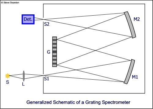
When the prism in Figure 1 is replaced with a reflecting diffraction grating to separate spectral lines S2(λ) in the above example, the two lenses L1 and L2 are usually replaced by two mirrors M1 and M2. These then produce an image of the entrance slit S1 onto the imaging plane B defined above. A general grating spectrometer schematic is shown in Figure 2 below. This is known as the Ebert configuration (see later).
Fig. 2 Reflection Grating Spectrograph Design
Figures 1 and 2 represent the two basic “classical designs” for a typical optical spectrometer, the first using refractive optics (a prism and lenses to produce a spectrum) and the second using reflective optics (a diffraction grating and mirrors to produce the spectrum). There are several different variations on these basic layouts, which are designed to perform different functions, and these are introduced now.
But first, a word about mountings. This is a term that we can meet in technical literature and a spectrograph “mounting” is often used in design discussions. The name simply refers to the particular layout and arrangement of the different optical, and even mechanical, components making up the instrument. These components consist of an entrance slit, the collimating and focusing optics, some kind of dispersing element (a prism or grating) and the light detector.
The term mounting probably arose from the time when spectrographs were quite large devices and had to be “mounted” onto a laboratory bench or at the focal plane of a large telescope. Astronomers were very keen to be among the first scientists to adopt the use of spectrographs with telescopes in their explorations of the universe. The sheer physical size of these instruments at that time meant that they had to be somehow mounted and physically supported in some way at the telescope focus.
A wide variety of different spectrograph mountings still exist today. Some are very popular ones in regular use in research labs and in field studies, as well as being connected to telescopes, often via optical fibres. Other types are more specialised mountings that are only used for very specific applications. Others again are little more than laboratory curiosities or museum exhibits today. Some examples of the different types of spectrograph mountings are described below.
The Littrow Mounting
As the focal length of the classical spectroscope outlined above increases, the device becomes physically much larger, and especially for a prism spectrograph the bent straight-through design becomes unwieldy and impractical with focal lengths greater than about half a metre or so.
The Littrow design is a useful mounting to replace the classical spectroscope shape at these longer focal lengths. It can also be used, and in fact is used, with spectrographs of smaller focal lengths, almost always with diffractive components (gratings).
In the Littrow design, the light rays are folded back more or less along the same optical path towards the entrance slit. The Littrow mounting for a prism spectrograph can be seen in the following two mountings, the first with a lens functioning both as the collimator and focuser, and the second with an off-axis mirror performing both functions. In both cases the dispersion element is a 30° prism, with a silvered reflection coating on its rear face, so that the light retraces its path back through the prism and the total dispersion is equivalent to a 60° prism.
Fig. 3 The Littrow Prism Spectrograph Design
Fig. 4 Variant on Fig. 3 with an Off-axis Mirror
In the mirror version of this mounting (Fig. 4) a small 90-degree prism is often added to intercept the dispersed rays just before the focal plane (as shown in the figure) with the detector positioned at the side of the spectrograph. This avoids having entrance and exit slits at almost the same point which is usually difficult to achieve due to the physical size of components.
Diffraction grating versions of the above two mountings are identical to Figures 3 and 4 above, but with plane reflection gratings replacing the 90 degree prism. In principle, transmission gratings could also be used in these two designs but never are since a reflective grating design is far easier to implement practically.
As a general rule, reflection optics (mirrors) are to be preferred over lenses, owing to the intrinsic problem of chromatic aberration with refractive components. Nevertheless, mirrors too come with trade-offs concerning optical aberrations. The off-axis parabolic mirror in the Littrow design in Figure 4 is often replaced with a spherical mirror in order to reduce cost, but this comes at the expense of introducing spherical aberration and astigmatism. The Littrow design is a very compact mounting, and the whole spectrometer can be built into a tube or box that in many cases can be not much wider than the width of the grating itself. This type of mounting is popular with amateur spectroscopists and astronomers who are recording the spectra of stars, nebulae and other celestial objects. A good example is the LHIRES III design marketed by Shelyak Instruments for the last several years for active amateur astronomers.
Two views of a quick and simple benchtop Littrow mounting setup can be seen in Figures 5A and 5B purely for demonstration purposes. The various components have been secured to a home-made optical table. For those interested, construction details on how to make such an optical table are found in this post.
Fig. 5A
Fig. 5B
Note that here is no slit being used in the purely demo spectrometer mounting above. The 45° prism redirects light from the tungsten lamp through the telephoto lens to the grating, where it is reflected and dispersed back through the lens and the lamp’s white light spectrum is then projected onto a white card.
The Ebert Mounting
This mounting is one of the more important types for the construction of spectrographs and monochromators in the scientific research lab and this very brief description is limited to grating types since these are by far the most common. The mounting was first explained by Heinrich Ebert and published in the Annalen der Physik in 1889. It was subsequently “rediscovered” by W. G. Fastie who added modifications to the design and published his findings in the Journal of the Optical Society of America in 1952. It is therefore known as the Fastie-Ebert mounting (or to be more historically correct the Ebert-Fastie mounting).
The basic difference between this mounting and the Littrow configuration is the presence of two optical elements (or two parts of the same optical element) that are used both to collimate and to focus the light source. A schematic of this mounting is shown in Figure 6.
Figure 6
Several variations on the Ebert-Fastie design exist, with some spectrometers using a single mirror and others having two separate mirrors. The latter are the most common.
An attractive feature of the design is that although spherical mirrors are used (and in many cases they are used off-axis which makes matters worse), any spherical aberrations produced by the first (collimating) mirror are largely cancelled by opposing spherical aberrations coming from the second (focusing) mirror. Coma introduced by the first mirror can also be quite large, but it is largely removed by opposite-working coma originating from the second mirror (or from the opposite side of the same mirror if one single mirror is being used). Thus spherical aberrations are not usually corrected for in this design, but are compensated for in the obvious symmetrical layout.
It must be emphasized, however, that this is only the case for what a called small Ebert angles i.e., the angle of entry of a ray of light at the entrance slit relative to the normal. As long as this angle remains small, and relatively large focal ratios (f/numbers) are used, then the effects of coma, which is the principal drawback of the Littrow mounting described earlier, are largely eliminated.
Unfortunately the requirement to use large f/numbers means that the overall speed or throughput of the spectrograph is relatively low. As a result, long exposure times of minutes, or even hours, were needed in the past using photographic film plates, in order to obtain good quality spectra close to the theoretical resolving power. Nowadays this is not too much of a problem with modern highly sensitive back-illuminated CCD detectors, capable of recording extremely weak emission from a sample.
As indicated above, there are a several variations on the Ebert-Fastie design, and we now come to perhaps the most popular…
The Czerny-Turner Mounting
The Czerny-Turner mounting in its standard form (Figure 7) has two separate spherical mirrors, usually in the same plane, and the entrance slit and detector are located on either side of the grating, closely similar to the Ebert-Fastie design described above.
Fig. 7 The Czerny-Turner Mounting
A practical variation on this mounting is the “crossed” Czerny-Turner design (Figure 8) which is very popular for modern spectrometers today with focal lengths less than 0.25 m and with mini fibre-optic instruments. With this design the optical bench has the two mirrors angled in such a way that the diverging beam from the input slit and the focused light beam heading toward the detector cross each other. In practice this provides certain advantages in that it is much easier to insert light baffles at various points on the mounting to reduce scattered stray light.
Fig. 8 The Crossed C-T Mounting
The crossed Czerny-Turner configuration is the design used in the Oriel Instruments MS125 1/8 m spectrograph described in another post and pictured here in Figure 9:
Oriel (Newport Corp) MS125 Crossed C-T Design
In addition to the Cerny-Turner mounting, which is itself a variant of the Ebert-Fastie design, other variations based on the Ebert-Fastie exist. Examples are the Newtonian-Ebert mounting and the Pfundt modification, but these designs are highly specialized and and will not be mentioned further.
Constant Deviation Mountings
Constant deviation mountings are a special kind of spectrograph configuration and are more often used with prisms than with gratings. They are especially useful as monochromators when it is necessary to have the emergent light beam exit in a fixed and constant direction. The mounting is usually set up on a turntable to achieve this and rotating a prism-mirror combination allows different wavelengths to fall on the exit slit in a fixed position. They are not in widespread use in the research lab today but are briefly mentioned here for the sake of completeness. The simplest design is the Wadsworth mounting in which a 60° prism is combined with a plane mirror. Two versions of this design are shown in Figure 10, the first using lenses to collimate and focus, and the second using mirrors to collimate and focus. Both designs have the base of the prism attached to a plane mirror which extends on one side to intercept the refracted light beam.
Fig. 10A Wadsworth Mounting - Lens Version
Fig. 10B Wadsworth Mounting - Mirror Version
In the mirror version above, a very compact mounting can be achieved through careful choice of the position of the prism and the mirror.
A constant deviation spectrometer can also be made by combining in line two or more 60° prisms of different glass compositions. This is known as a direct vision spectroscope, and is employed as a very small, usually hand-held, spectroscope for visually observing the spectra of relatively bright light sources. A good example is the “Handheld Spectroscope” which used to be available from Edmund Optics but which is, apparently, no longer in their catalogue (although there are other lower cost alternatives from online sources).
Direct vision spectroscopes are useful and compact little instruments for visually identifying absorption and emission lines in a variety of light sources. They usually feature a 2, 3, 4 or even 5-element prism train as shown in Figure 11 here:
Fig.11A
Fig. 11B
Concave Grating Spectrographs
A concave grating is basically a concave mirror that disperses light in addition to focusing it. Ruling a grating on a concave mirror instead of on a plane surface mirror means that it can act as its own collimator and focuser. As a result, the spectrograph mounting can be reduced to its three essential components: a slit, the grating and the detector.
A practical example of a concave grating was first demonstrated in a paper by Henry Rowland in 1883, who introduced their properties to the scientific community in a short paper a year earlier. Rowland showed that if the entrance slit and the grating both lie on a circle whose diameter is the same as the radius of curvature of the grating, and if the grating surface is tangent to this circle, then a focused spectrum will be produced on the same circle. This circle is referred to as the Rowland circle:
A concave grating in real terms consists of a series of parallel grooves ruled onto the surface of a spherical concave mirror. Since the mirror surface is curved, the distance between the lines along any arc on the surface cannot not constant. However, the spacing is constant along a chord of the arc when seen from infinity. In this way the same grating equation used for plane gratings, namely d(sinα ± sinβ) = mλ, will still apply. This time d is the groove distance as measured along a chord across the grating arc. Another way of describing this is that the grooves’ positions are the intersections, with the spherical mirror, of a series of equally spaced parallel planes. One of these planes (the one passing through the centre of the grating surface) also contains the optical axis of the grating.
Historically, spectrographs with concave gratings based on the Rowland circle found applications for deep UV spectroscopy. This is because glass lenses absorb too strongly in the UV and also the reflectivity from mirrors is very low. Having only a slit, a grating and a detector in this experimental region was a distinct advantage!
Advantages and Limitations
Rowland Circle mountings do have their limitations however. In practice, good focus is achieved only over a very narrow range of wavelengths and, as one would expect with a concave spherical mirror, astigmatism can be severe at large angles away from the optical axis. Slit images with a Rowland mounting are strongly curved and to make matters worse the degree of curvature depends on the diffracted wavelengths. In addition, only a small fraction of the dispersed light is captured, unless the exit slits are longer than the entrance slit.
The principal advantage of a Rowland mounting is that it has the absolute minimum number of optical components required to design a complete spectrograph. Since any additional optics for collimation and focusing always add aberrations and reflection losses, this can be a real benefit as mentioned above for recording spectra in the deep UV.
Modern spectrographs today that use concave gratings avoid the above limitations in the original Rowland design by employing what are called Variable Line Space (VLS) gratings. Such a grating consists of a pattern of straight, parallel grooves with a controlled, but variable and non-periodic, spacing between each groove. As a consequence, VLS gratings are able to modify the positions of true focus at the detector.
Applying this modification to the Rowland mounting means that the field of focus can be virtually flat and linear over the spectral range of interest. Such a system is ideally suited for modern linear CCD and CMOS detectors in widespread use today. Instruments incorporating these improvements are known as Flat Field spectrographs. A good example of a flat field spectrograph is the FICS (Fixed Imaging Compact Spectrograph) shown in the two images below. It is marketed by Oriel-Newport Corp. The FICS is described in more detail in this article.
This concludes our brief historical walkthrough of the various design changes made to the spectroscope over the many years since its original invention by Kirchhoff and Bunsen in 1859.
Many technical details have obviously been omitted for simplicity and brevity and some of the more obscure types of mountings avoided entirely. But I hope I have been able to summarize the essential historical development and evolution of a truly amazing invention that has been so crucial to scientific progress for the last 160 years.
3 Minute ReadAbsorbance In very general terms, Absorption Spectroscopy is the spectroscopic technique that considers what happens when electromagnetic radiation of any wavelength passes…
9 Minute ReadWhat is Fluorescence? Before we can consider what is fluorescence in scientificterms, we must mention the general process of luminescence. Luminescence is defined…
2 thoughts on “Spectrometer Designs”
Tuan Duong
I’ve been watching quite a few videos about the “drone” phenomena in New Jersey, and I thought some serious investigators should carry a spectrometer to get the spectral signature of the light in the night sky to quickly eliminate the common light sources. Hopefully, the mysterious objects may have a unique spectral signature of their own. (Or the investigators can tell that the drone’s lights are made here on Earth.)
I suppose spectral analysis may require an ultra-stable platform, but there should be a way to obtain a rough spectral signature in the field.
Thanks for your interest. I heard about the drone story but haven’t followed it in any detail. The problem, as you mentioned, would be to obtain a reliable spectrum of the drone, especially if it is moving around. None of the designs I mentioned in the post would be suitable, with the possible exception of the direct reading spectroscope. But this is hand-held and getting a stable reading would be a challenge. A thermal imaging camera could be a possibility; many models operate in the near IR where molecular signatures might be able to be identified. But I’m not an expert with those particular sensors.
Steve