Introduction
In several previous posts the physical principles describing the fluxgate magnetometer were introduced. We went on to construct a simple magnetometer based on a single fluxgate sensor, available from FG sensors in Slovenia. This was installed in a small thermos flask to provide some reasonable means of keeping the temperature fairly constant and data from the sensor were processed with an Arduino and a Raspberry Pi.
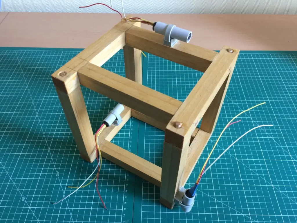
In this post a more complete implementation of a magnetometer is presented which incorporates three fluxgate sensors. These sensors are oriented along the three orthogonal axes XYZ. In this way we are able to interpret fully any terrestrial magnetic field variations and geomagnetic storms.
It is important to note that this is a complete and independent project in itself. It is separate from an earlier “Aurora Monitor project” that was previously described in four parts in recent months. Both of these projects were developed totally separately and independently. This particular project has been named SAM III to acknowledge the work of Karsten Hansky, Dirk Langerbach and Whitham Reeve for their work on magnetometers with three fluxgate sensors, oriented along the three orthogonal XYZ axes.
Additional acknowledgements are provided when required and when appropriate.
SAM III in a Few Words
The SAM III is the brainchild of Karsten Hansky and Dirk Langenbach. It is a sophisticated semi-professional geomagnetometer and full details for the construction of the SAM III are available here. Hansky and Langenbach’s site contains complete information for the construction of the SAM hardware together with the necessary free software and user guides required to set up and configure the device. Links are provided for all the necessary documentation and any updates, and a general tutorial on geomagnetism written by Whitham D. Reeve is included.
For those amateur scientists and experimenters interested in setting up a geomagnetic observatory, the SAM III can be purchased in the form of a kit from Whitham Reeve’s site at https://www.reeve.com/SAMDescription.htm. The site also proposes single- and dual-axis versions of the SAM III monitor (SAM I and SAM II respectively). However, much of the focus and attention is on the SAM III because with three matched sensors we are able to characterize fully any daily changes in your local magnetic flux density along the three XYZ axes.
SAM III Construction Details
This project does require some familiarity with electronics and some reasonable soldering skills. If you have never held a soldering iron before and have never soldered discrete electronic components (resistors, capacitors, IC’s etc.) onto a printed circuit board, then this may not be the right project for you. It may be wiser to learn the basics and essentials of soldering on a more simple project, many of which can be found online, before attempting to build a SAM.
Fortunately, for experimenters with previous soldering skills, this project should pose no problems whatsoever.
Populating the PCB's
The SAM Construction Manual, the software setup guide, useful tips and ordering information for the complete kit can all be downloaded here from Whitham Reeve’s site.
If you are like me and you hate reading user manuals and want to get started straight away, then STOP! This is the one time when you really need to read the manual and understand the construction details sufficiently well before proceeding. For those attempting this project and building the kit, read through all the documentation first before even thinking of picking up your soldering iron.
Full explanations are given down to the smallest detail in well prepared and written manuals and guides. These include populating the PCB’s with all the components, connecting power, checking the right voltages are present at various points on the boards, testing, adjusting and uploading the microcontroller firmware.
The next series of images depict some of the different stages during my own construction of the SAM III boards. (For full details and much more information, refer to the construction manual.)
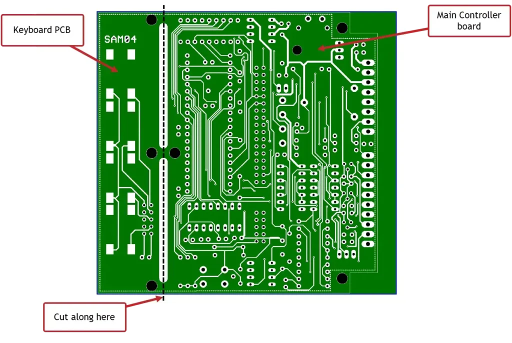
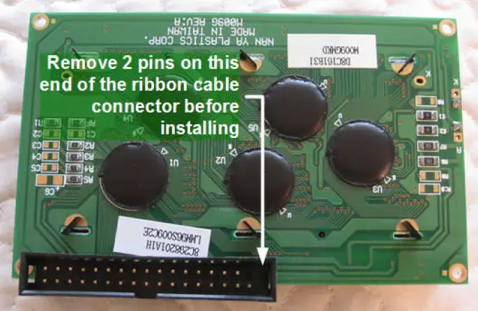
Above shows two of the unpopluated PCB’s when you receive them. They are manufactured as one piece but have to be separated by cutting the three “bridge points” as shown along the dotted line. The other board contains a small four-row liquid crystal display, the underside of which is shown below, courtesy of Reeve.com, and is used with permission:
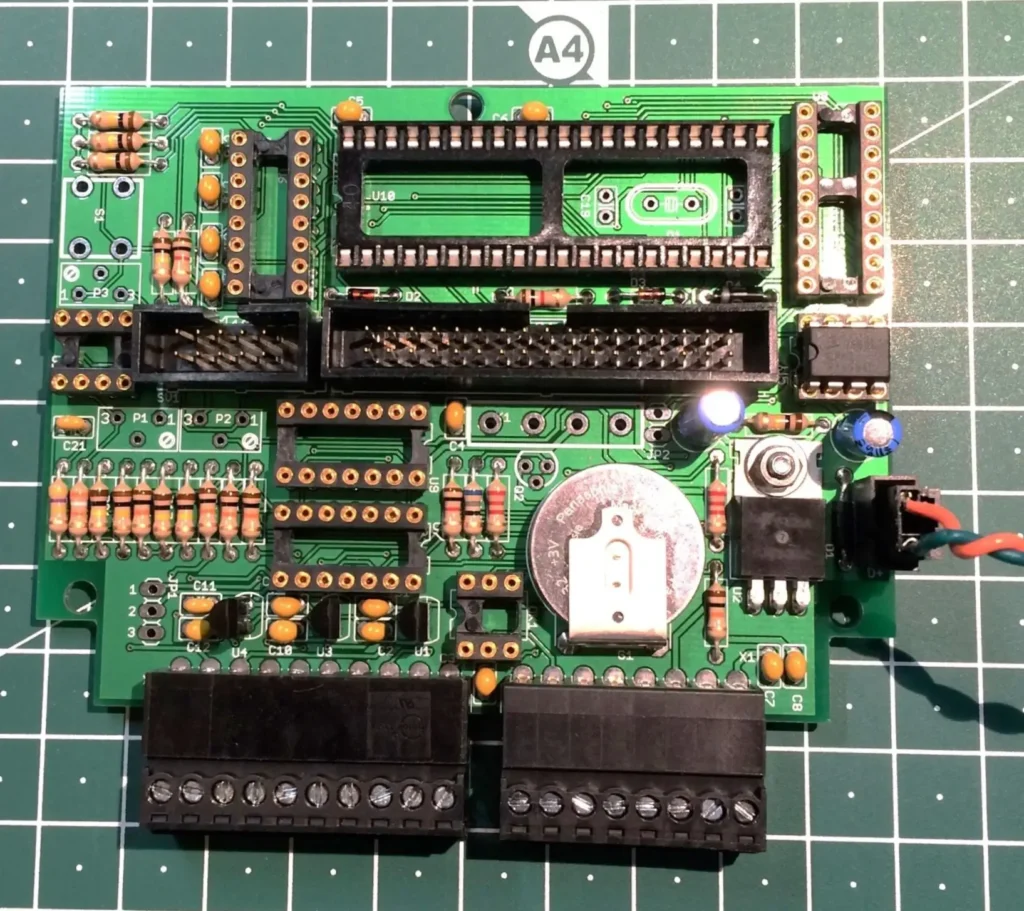
The following image shows my version of the controller board with all passive components (resistors, capacitors, diodes, etc.) soldered. At this stage the board can be supplied with power to check for correct voltages at different points in the circuit as you follow the instructions in the manual.
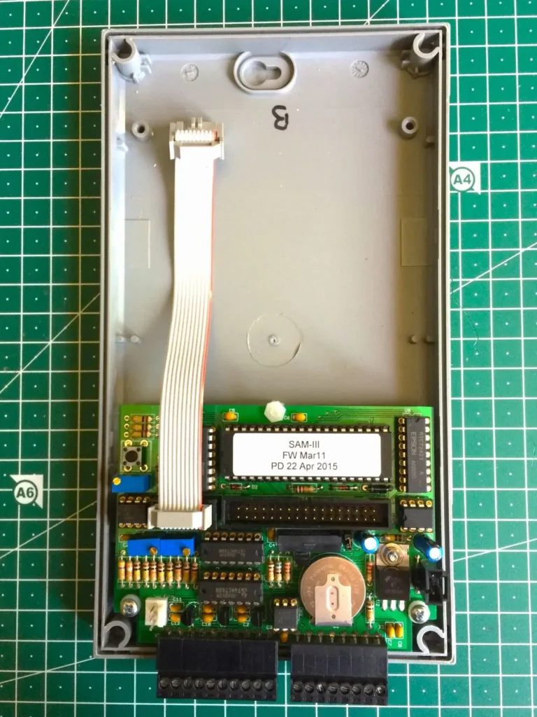
Below is the completed controller board. All the IC’s have now been inserted and voltage regulators, ribbon cable headers and connectors fixed onto the board. The 3V lithium battery is there to provide backup power for a real time clock.
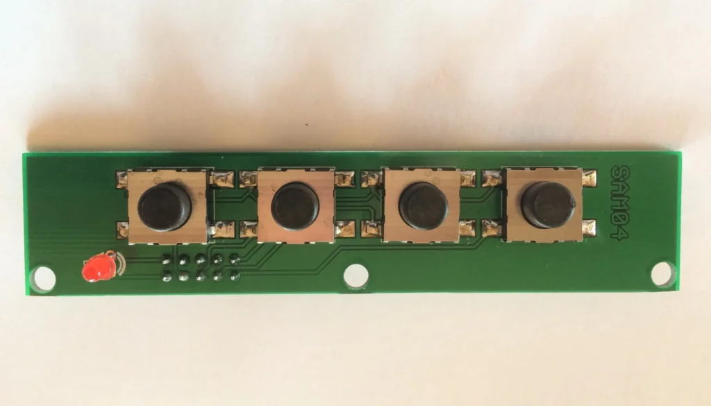
Next is an image of the completed keyboard. This is the simplest of the three PCB’s to populate, with its 4 push buttons for Command Mode, Calibration Mode, Software Reset and Display Backlight, together with a red on/off LED:
Connecting the PCB's
The three separate modules (Controller board, Keyboard and Display board) are connected via ribbon cables as shown in the following schematic, courtesy of Reeve.com and used with permission:
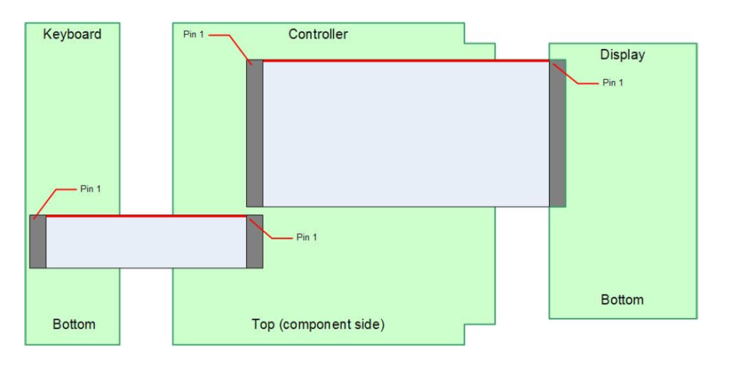
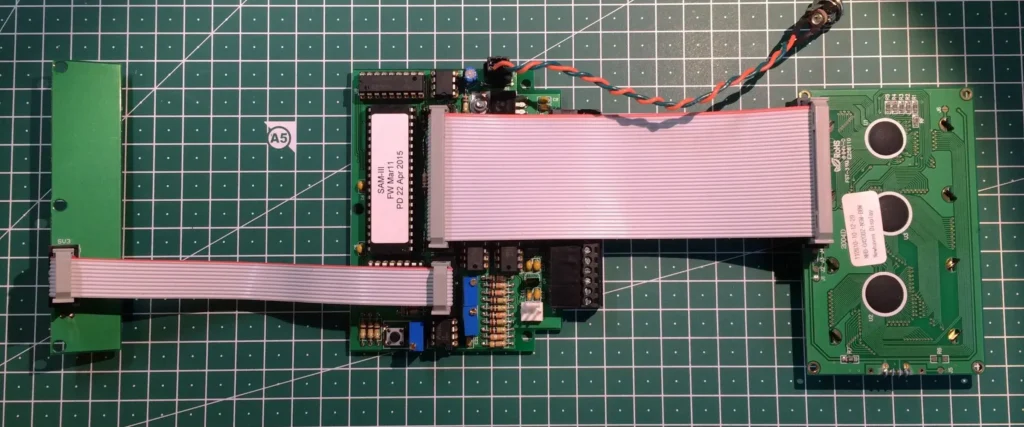
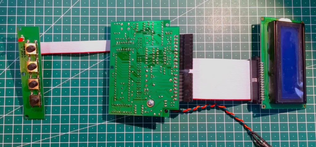
And the real connections can be seen here in these two images, topside and reverse side:
Installing in an Enclosure
If you build the SAM III kit you have the option of adding its purpose built enclosure, a picture of which is shown below. Alternatively you can choose any appropriate enclosure that can accept the three boards.
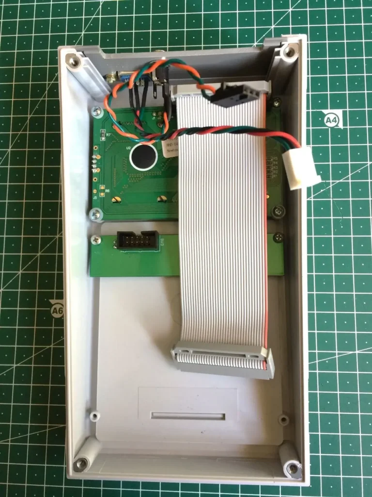
The following 2 images depict the SAM III display board and keyboard correctly installed in the top half of the enclosure (left), and the controller board installed in the bottom half (right).
I am deliberately skipping over several steps towards the final construction stages because these are already very comprehensively covered in the SAM construction manual. The wiring of a Serial Port cable, testing voltages and making adjustments on initial power up, and loading the operating system firmware, are not mentioned here for the sake of brevity.
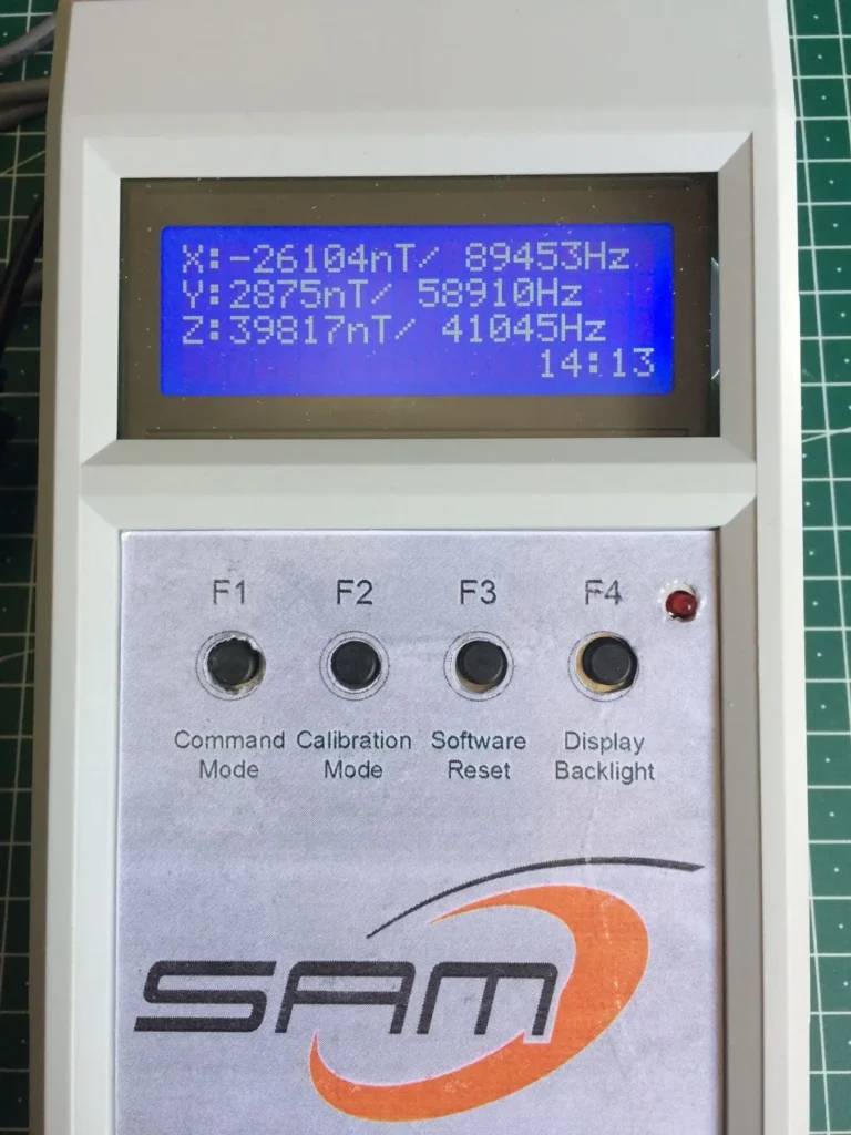
But when the completed boards are finally installed in the enclosure, when connections to 3 fluxgate sensors are made, and when power is suppled, the display should light up and show something like this…
The X, Y and Z numbers are measuring the local magnetic field intensity (flux density) along these three perpendicular axes. The actual values, which are in nanoTesla (nT), do not mean much at this point since the sensors are on a test bench, not oriented correctly nor installed in their permanent location (more about that later). But the fact that we see some numbers for X, Y and Z means that the SAM III is functioning correctly. (The two numbers at bottom right represent local time in UTC.)
Next Steps
The final (Part 2) of this project will describe the installation of the fluxgate sensors in a permanent location with connections to the SAM III controller and briefly how the software (SAMView) is set up.
Coming soon…
