In part 1 we covered the construction of the SAM III boards, the connections between the boards and incorporated the boards into a suitable box.
In this post we move on to the three fluxgate sensors themselves. We explain how these have to orientated and positioned relative to one another in order to send reliable and self-consistent data to the SAM controller and, if desired, to a website.
Positioning the Sensors
As mentioned elsewhere on this site, an inconvenience with fluxgate sensors is their relatively strong temperature dependence. In order to minimize signal changes due to temperature variations, fluxgate sensors are aften buried underground to a depth of 1-2 metres. This can be common practice both with amateur and semi-professional installations.
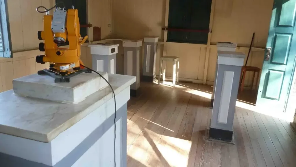
An alternative solution is to have the sensors in a controlled constant temperature environment. This approach can be extended, with institutional sites, to build a complete geomagnetic observatory, where the instruments are installed on solid vibration-free mountings in temperature controlled rooms. An example is this one located at the GFZ Helmholtz Centre in Potsdam, Germany:
In my much more humble (and less costly!) case, the SAM III sensors are installed in an insulated polystyrene picnic box, with an Arduino controlling the temperature using a small incandescent lamp. Full details of this enclosure have been more than adequately described in this post.
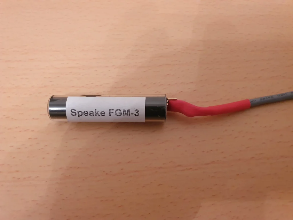
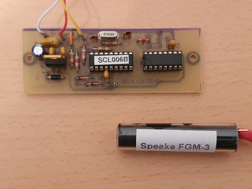
The SAM III construction manual devotes several pages (section XV) on wiring the sensors and hooking them up to the SAM controller box. These sensors were originally available from Speake & Co. in the UK but are now marketed by FG sensors of Slovenia.
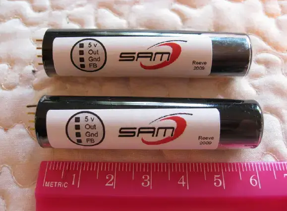
Two sensors are shown in the above image (courtesy of Whitham Reeve at reeve.com and used with permission). These original sensors, which came from Speake & Co. in the UK had 4 connector pins as shown in the picture. However only three pins are actually used (5V, Out and Gnd). The pin marked FB (feedback) is not needed for the SAM III and is in fact no longer manufactured by the new company FG sensors.
When wiring, it is highly recommended to use separate cables for each sensor in order to prevent crosstalk interference. Additionally, it is recommended to construct a non-magnetic support structure for mounting the sensors. This needs to be designed so that it physically separates each sensor by at least 15 cm (6 inches). Any closer and the sensors’ signals can interact with each other by proximity interference. This is explained in more detail in the SAM contruction manual.
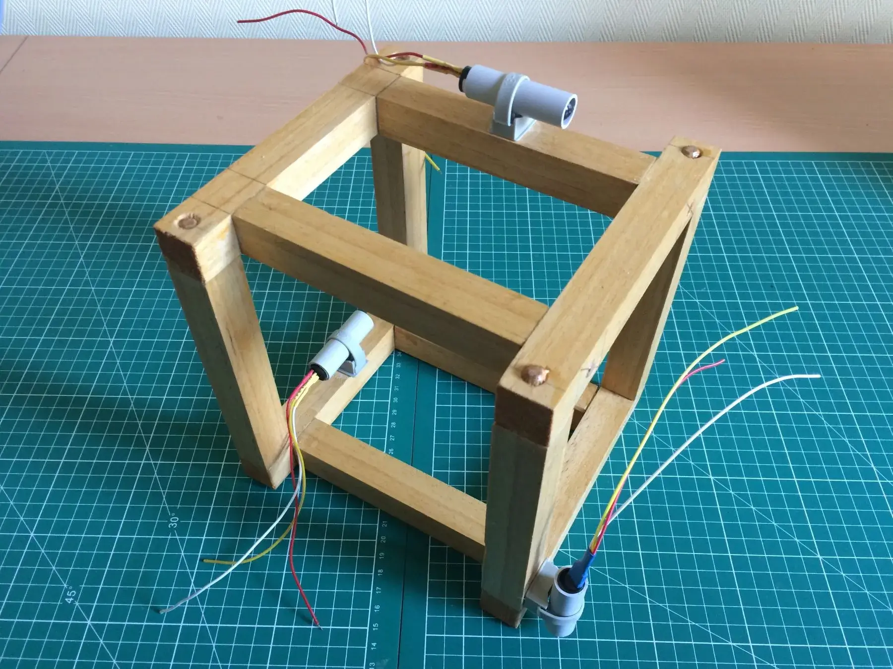
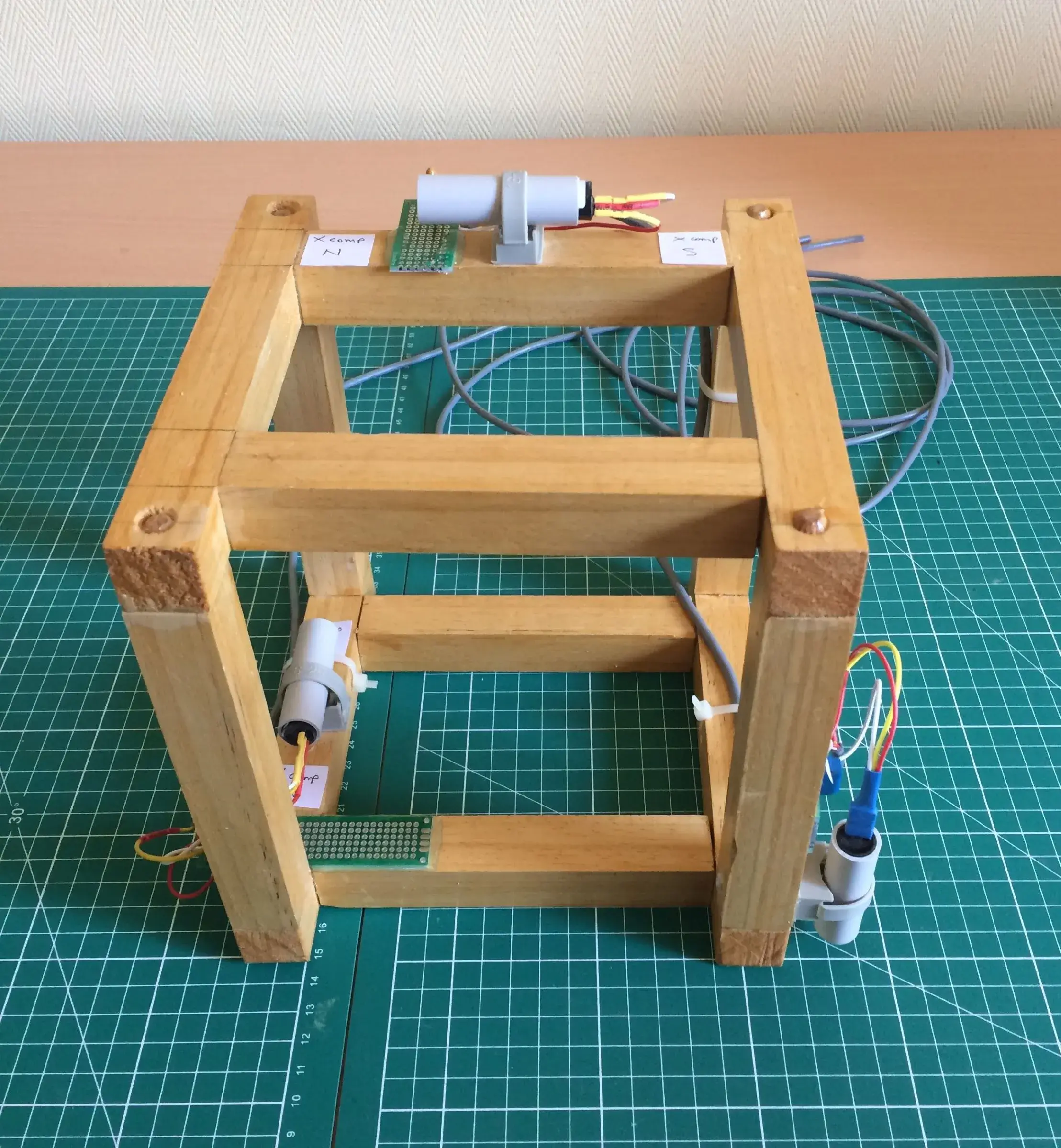
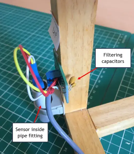
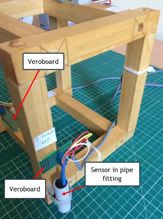
My own solution to separating the sensors and cabling them properly is given in the next few images. It uses a simple wooden frame to support the sensors – no ferromagnetic metal screws please! These are individuallly mounted inside standard household PVC pipe fittings of the right diameter as shown here:
A close up of one sensors can be seen in these next 2 images, where a small piece of veroboard, with a soldered terminal block, are used. Two filtering capacitors need to be soldered as close as possible to each sensor: a tantalum capacitor for low frequency filtering and a ceramic cap for high frequency filtering.
As before, more details can be found in the manual.
Software Setup
By this point, we should have a fully operational SAM III controller working. The fluxgate sensors are connected, working and installed in an appropriate temp-controlled housing, and magnetic field density readings are being transmitted and displayed.
We can of course leave things there, as they are. We can simply check the magnetic field values visually on the SAM III controller. But it is far simpler, and more instructive, to record the changes in magnetic flux density with time on a chart. And this is particularly important when we want to monitor magnetic storm conditions and the consequent appearance of an aurora. Any sudden swings in field density, from phenomena such as solar flares and CME’s, will avert you to sudden changes in geomagnetic conditions and when to expect the aurora over the next 24 hours. To do this, we can install SAMView.
SAMView
Full information on how to set up and install SAMView is provided here in a comprehensive guide from Whitham Reeve’s site at reeve.com. Software installation is straightforward, and the application provides regular updated plots of the X, Y and Z components of geomagnetic field intensity.