Introduction
In previous posts the fluxgate magnetometer was described. The frequency pulses from the fluxgate sensor were captured by an Arduino microcontroller then sent to a Raspberry Pi for further analysis and display.
One drawback with fluxgates is that they are also temperature dependent. One way to minimise temperature variations is to bury the sensor in your garden. This is, in fact, often performed by many researchers.
Another way is to keep the sensor in a temperature-controlled enclosure so that the magnetometer is only measuring changes in magnetic field intensity and signal changes due to temperature are eliminated or minimized. In this and the following related posts we describe the construction of such an enclosure with an Arduino being used to measure and control temperature and humidity.
But before we get on to the enclosure itself and how to control the temperature, let’s first take a quick look at how to measure and record temperature (and also humidity), with this extremely useful microcontroller – the Arduino.
Connections and Setup

The above schematic is simply a test circuit we are using before adding a means to control the temperature. This example uses the Arduino UNO, or an Arduino clone which is a bit cheaper. The circuit works equally well with its little brother, the Arduino Nano.
The DHT22 is a popular temperature and humidity sensor that costs less than 5 dollars. The 1602 LCD is a widely available liquid crystal display module, also costing just a few dollars, that prints characters in a 16×2 matrix. The various connections needed are shown.
The DHT22 has three pins: positive, negative and output. These are connected, respectively, to the 3.3V, GND and Number 2 pins on the Arduino. The four pins on the display are connected to GND, 5V, and the AnalogIn sockets A4 and A5 (black, red, purple and cyan coloured wires respectively).
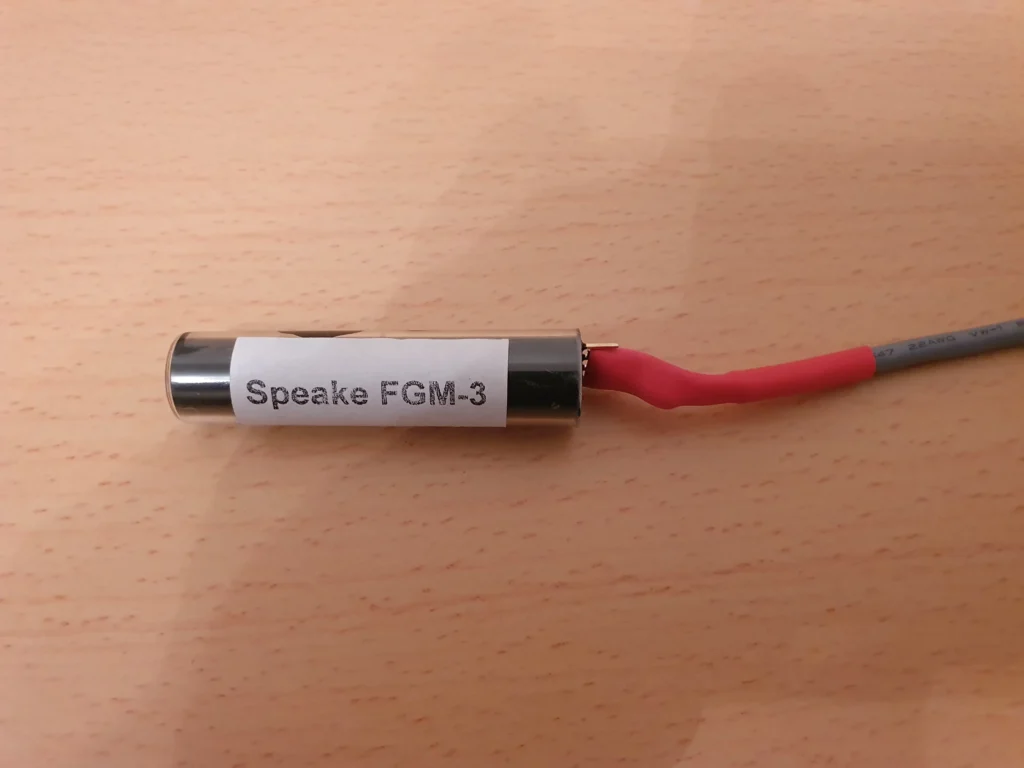
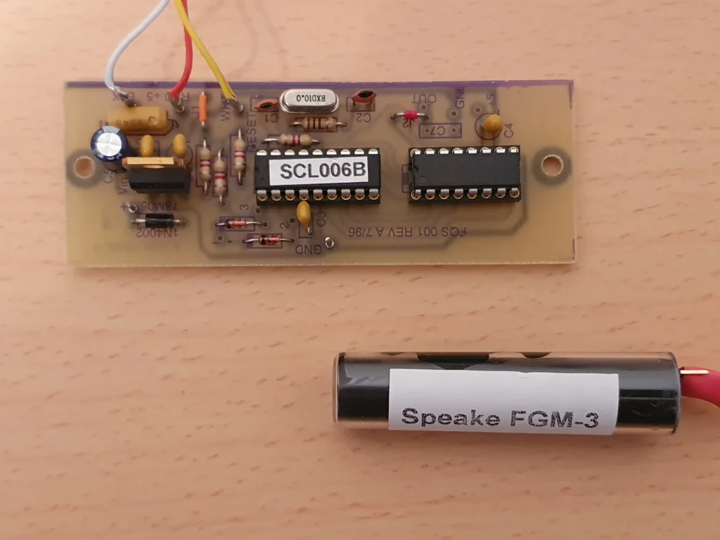
The real-world components themselves are shown in these pictures:
Arduino Code
Now I am definitely not a programmer. In fact, I am pretty much a total beginner when it comes to writing code for the Arduino or the Raspberry Pi.
But I have found that the best way get into programming, especially for the Arduino, is to take a small snippet of code, to try to understand as much as possible what it does, then to modify it to the requirements for your own project.
There is a huge amount of material online and the Arduino IDE interface contains many libraries of common code routines that can be inserted into your own project code in order to get your program to work.
For complete beginners, with no electronics or programming experience, numerous YouTube tutorials are available. A useful one that I have used in the past is the Programming Electronics Academy run by Michael Cheich.
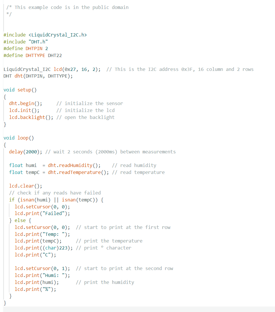
The code for the above circuit, where the Arduino takes in data from the sensor and sends it to the LC display, is shown here:
Results
This demonstration and sample code is fairly common and there are numerous examples online, several with help on how to get started for the beginner.
The video here shows the results. The values are slowly changing because I briefly applied a hair dryer to the sensor and breathed directly on it, in order to change temperature and humidity.
Next Steps
Part 2 of this project will add a heater to this circuit and determine if the temperature profile is stable. If necessary, a cooling fan may need to be included. These additional components will be used to measure and control the temperature within some pre-defined limits so as to keep the enclosure at constant temperature.
Watch this space…
Steve
Pingback: The SAM III Magnetometer - Part 2 -