This is the second part of a project to build an Arduino-controlled constant temperature enclosure. In the first part of the project we set up the Arduino microcontroller to receive temperature and humidity data from a sensor and then to send this data to a type 1602 liquid crystal display.
In this post we will now add a small heater (in the form of a 40W light bulb) and with the aid of the Arduino use a relay to switch the bulb on and off to maintain constant temperature.
Note that in the following circuit the liquid crystal display has been ommitted to simplify the circuit. It could be re-introduced in future. But for now, temperature recordings will be produced by an independent data logger.
The Components
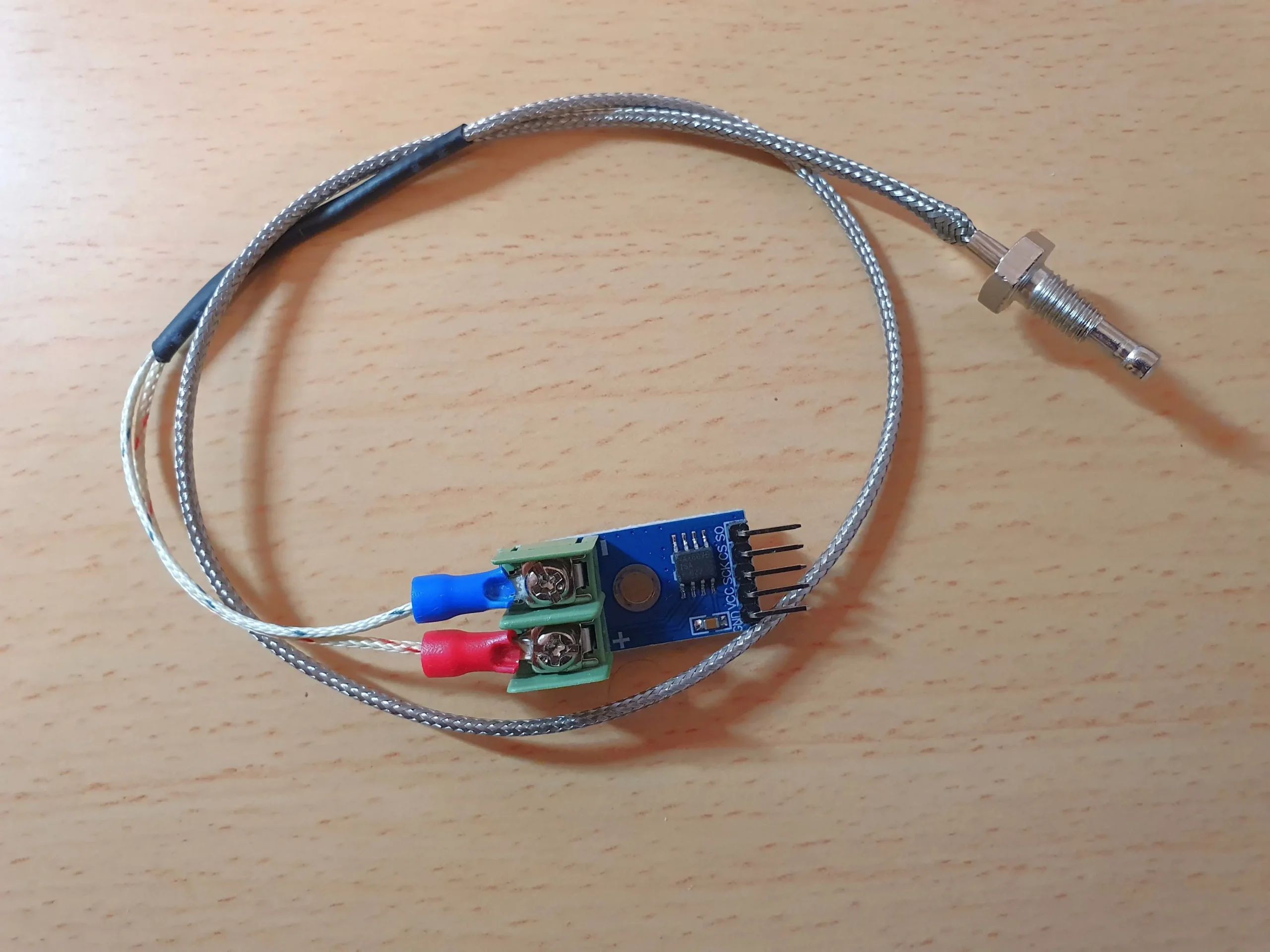
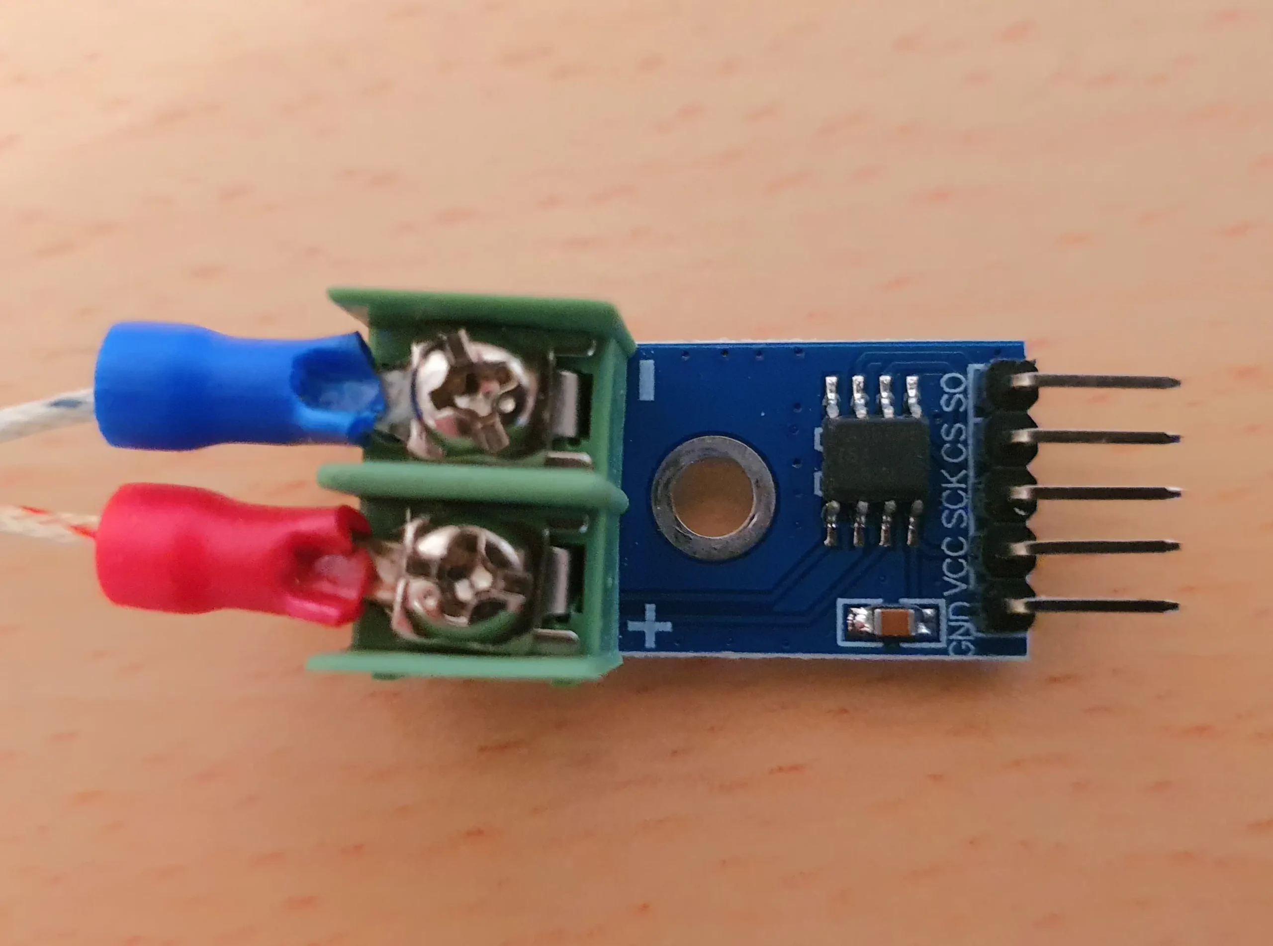
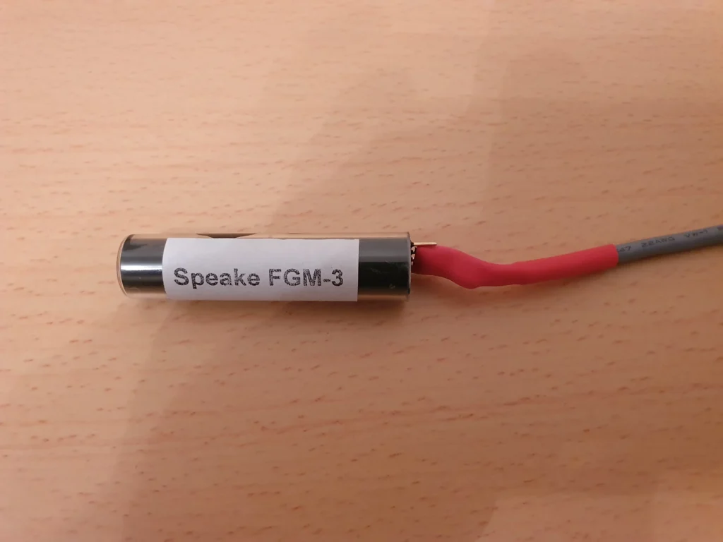
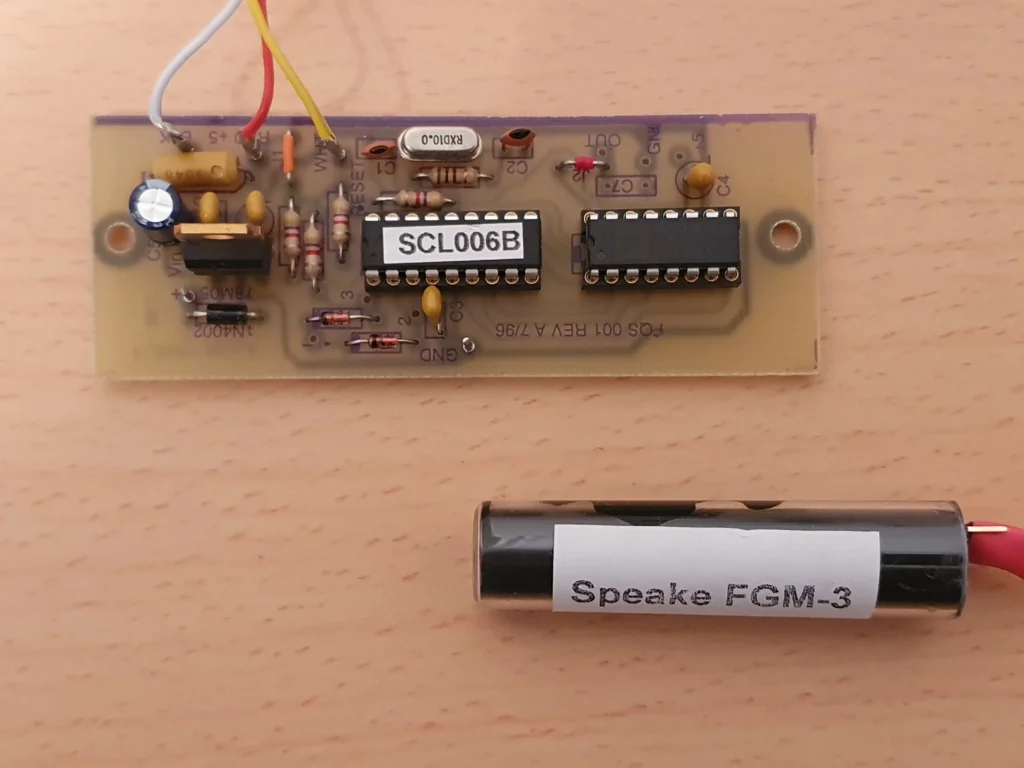
Since Part 1 was published, the DHT22 temperature sensor has been replaced with a K-type thermocouple which is more precise. At best, the DHT22 has an accuracy of ±2 degrees C, which was felt to be inadequate. The new K-type thermocouple, with a MAX 6675 control module (required for it to function), is shown in these two images, and appears to be more accurate from datasheets :
MAX6675 and Thermocouple
Close-up of the MAX6675 Module
The “heater” is simply a 40 watt light bulb screwed into an appropriate mains socket. This is fixed onto one of the internal walls of the enclosure. Note that LED light bulbs cannot be used since they do not provide any heat. An incandescent tungsten filament bulb must be used to provide some infrared energy. Fortunately these are still available and still inexpensive.
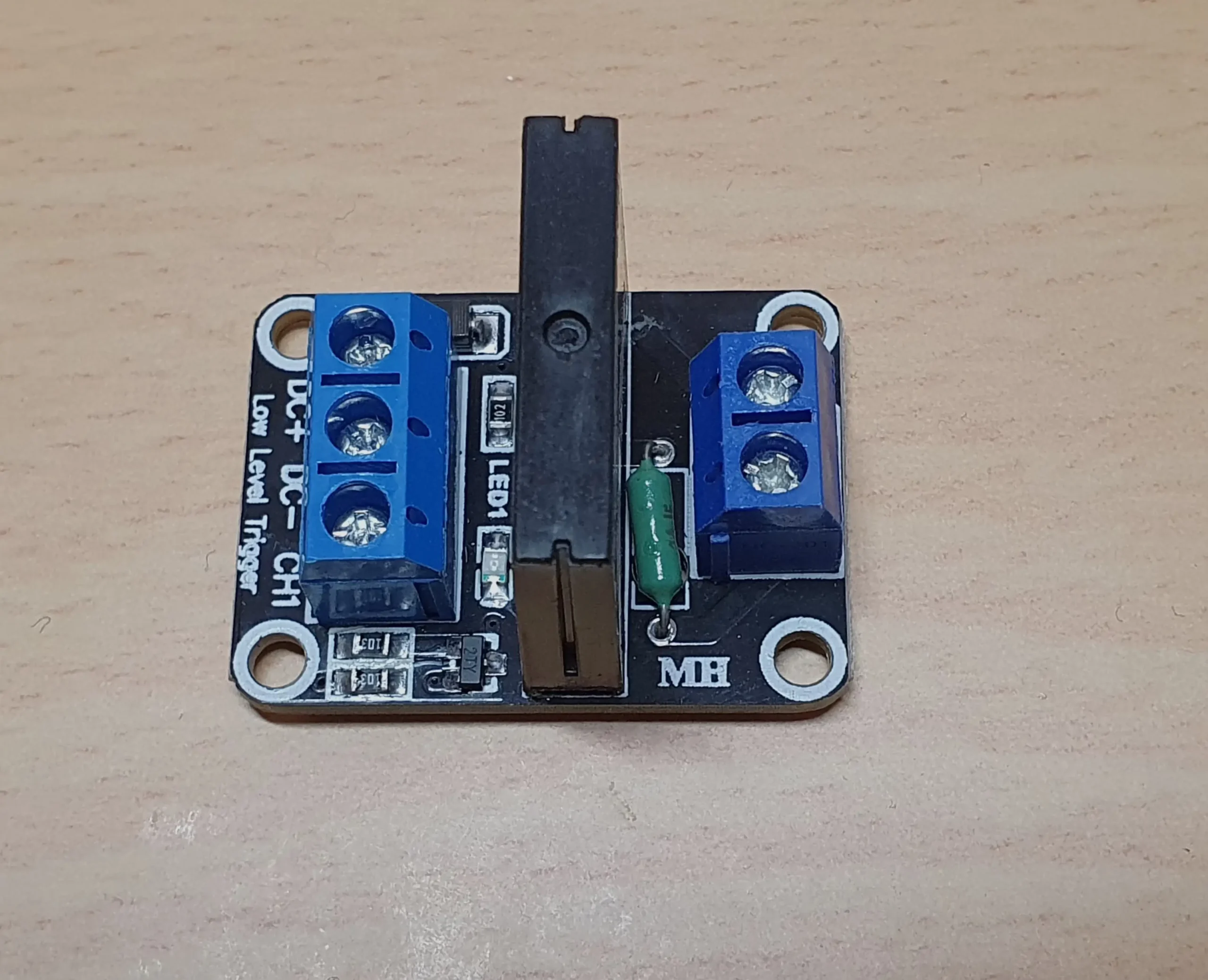
In order for the Arduino controller to switch the bulb on and off, a relay is required. Relays come in two varieties: mechanical and solid state.
Mechanical relays are electro-mechanical devices that employ an electromagnet to open or close a switch. They usually consist of a coil of wire (the electromagnet), a spring, and a contact that conducts the current. They are mostly found in industrial applications for handling large currents. We don’t really need such a high current component for this project. Furthermore, mechanical relays are prone to wear and tear since they have moving parts, and will eventually fail.
Instead, we shall use a solid state relay. This uses a semiconductor chip to switch the current. It can handle reasonable current loads and is the obvious choice for this project.
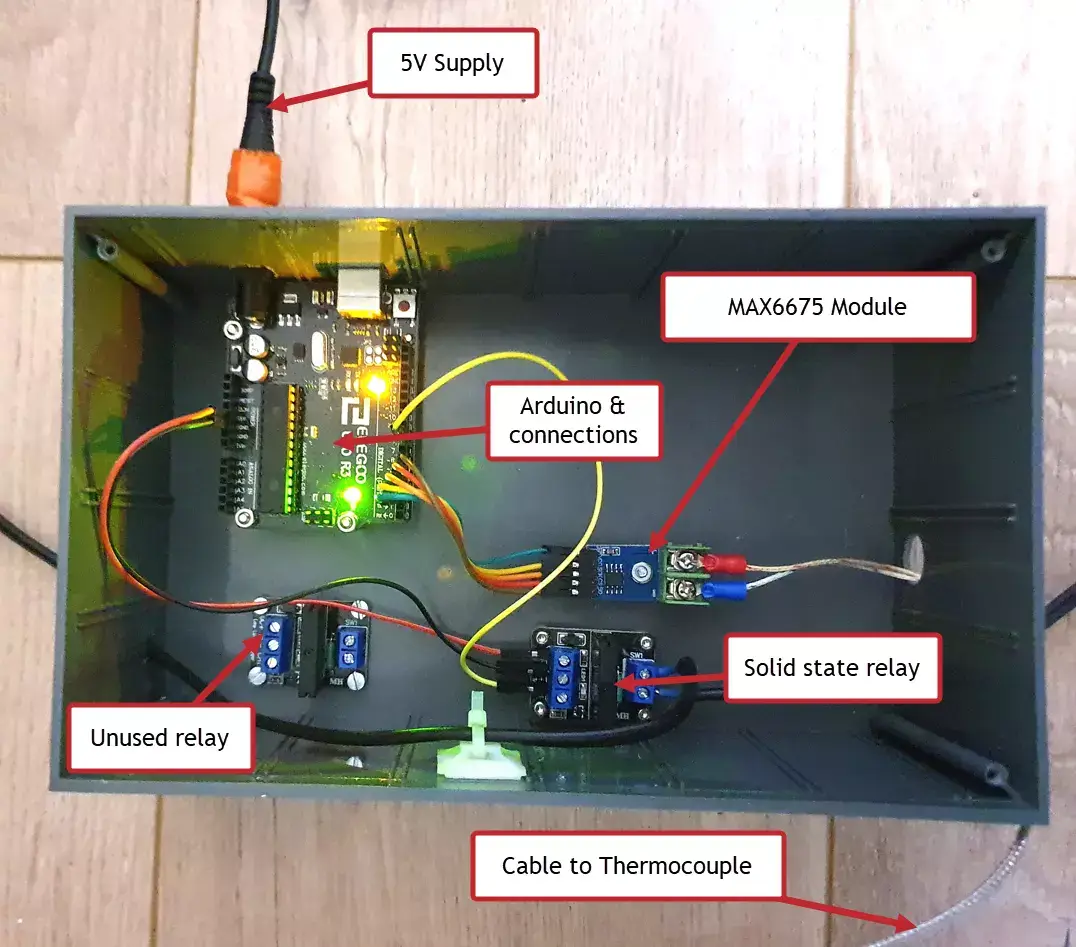
A picture of the actual setup is shown below, with the various components screwed into a plastic box typically used for housing circuit boards and other electronic components:
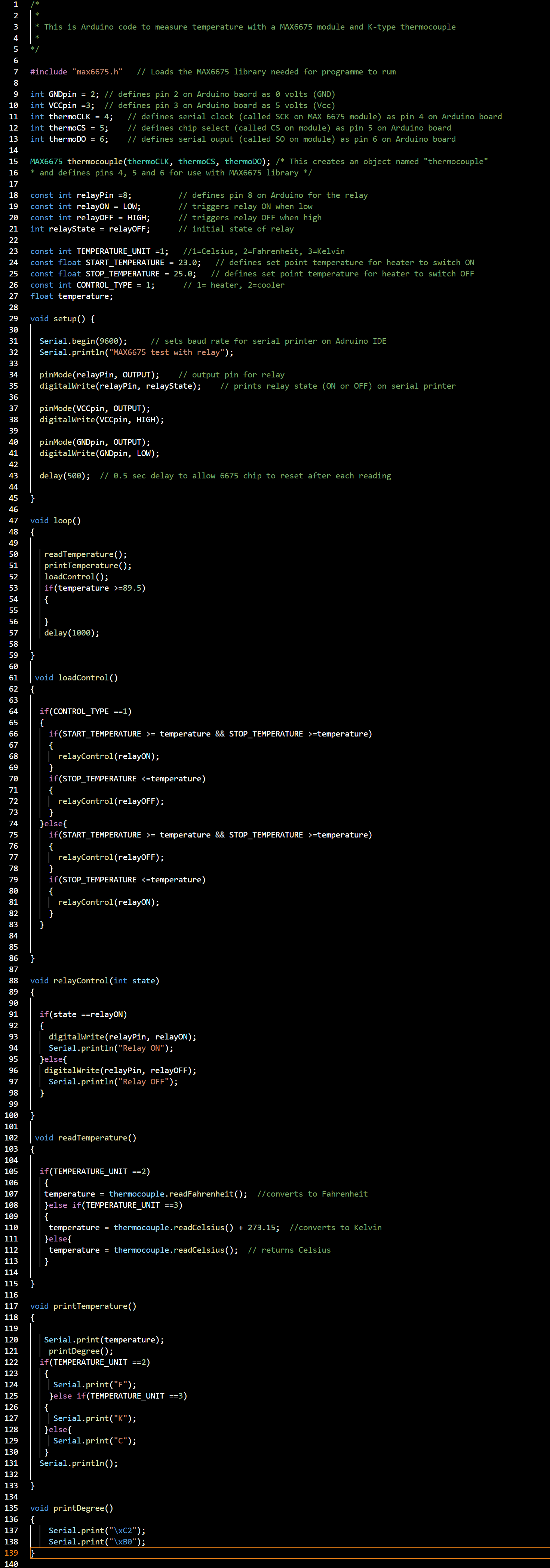
Arduino code
The code is shown below. Comments are in green after the // and are ignored by the compiler. The more comments you use, the easier it is to understand the program.
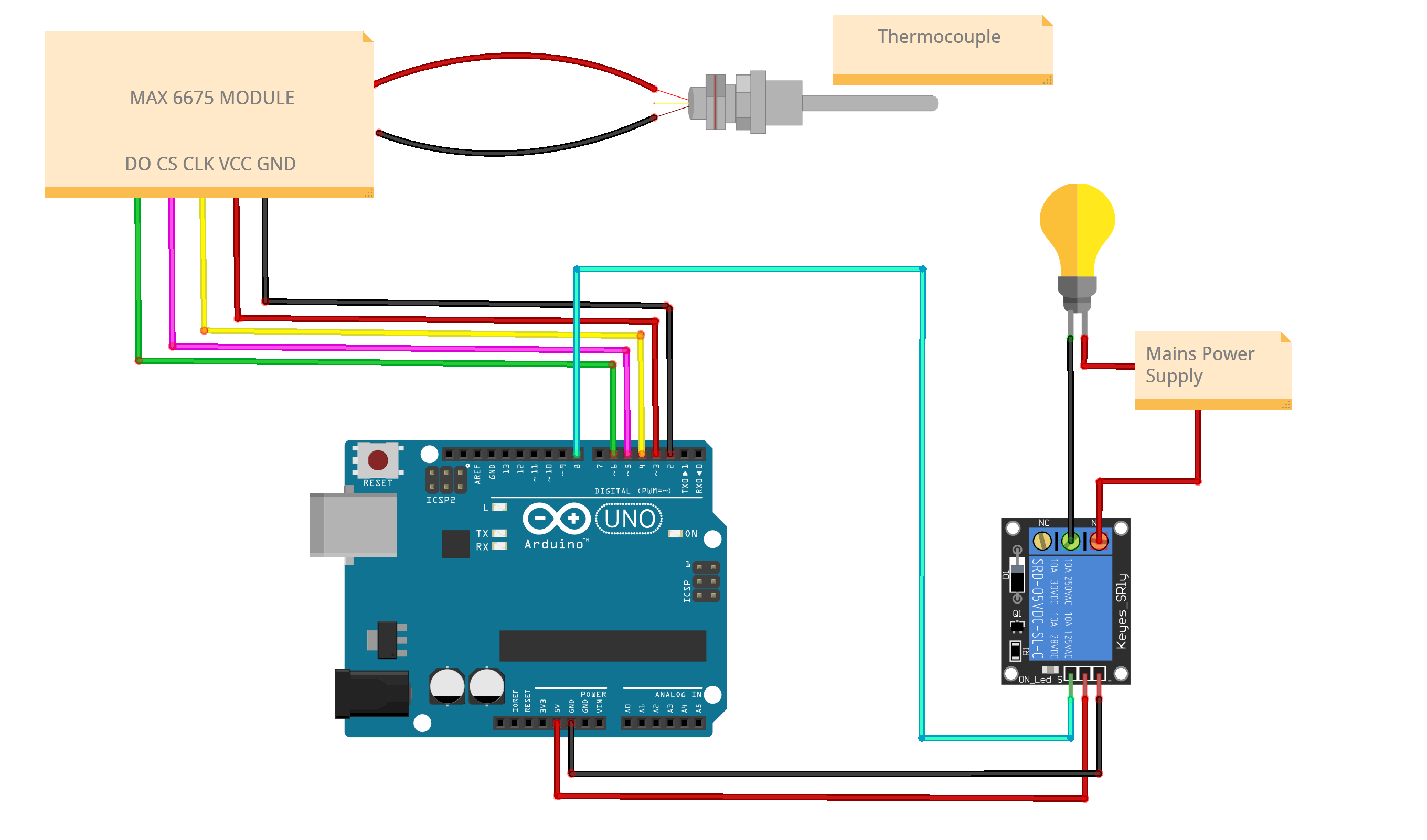
As shown in the schematic, the MAX6675 terminal connections are as follows:
GND → Pin 2
VCC → Pin 3
SCK → Pin 4
CS → Pin 5
SO → Pin 6
If connections are made to different pins, then code lines 9 to 13 need to be changed accordingly.
The Enclosure
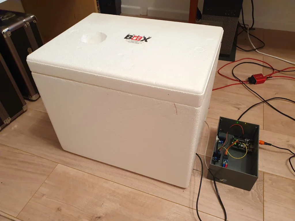
A thermally insulated picnic box is employed to minimize temperature variations as much as possible. The type normally used for keeping food and wine cool is the cheapest option and made of expanded polystyrene. The heavier duty hard plastic varieties are also an option but cost more. Furthermore, the cheaper polystyrene versions are easier to drill for passing cables, etc. An example is seen here:
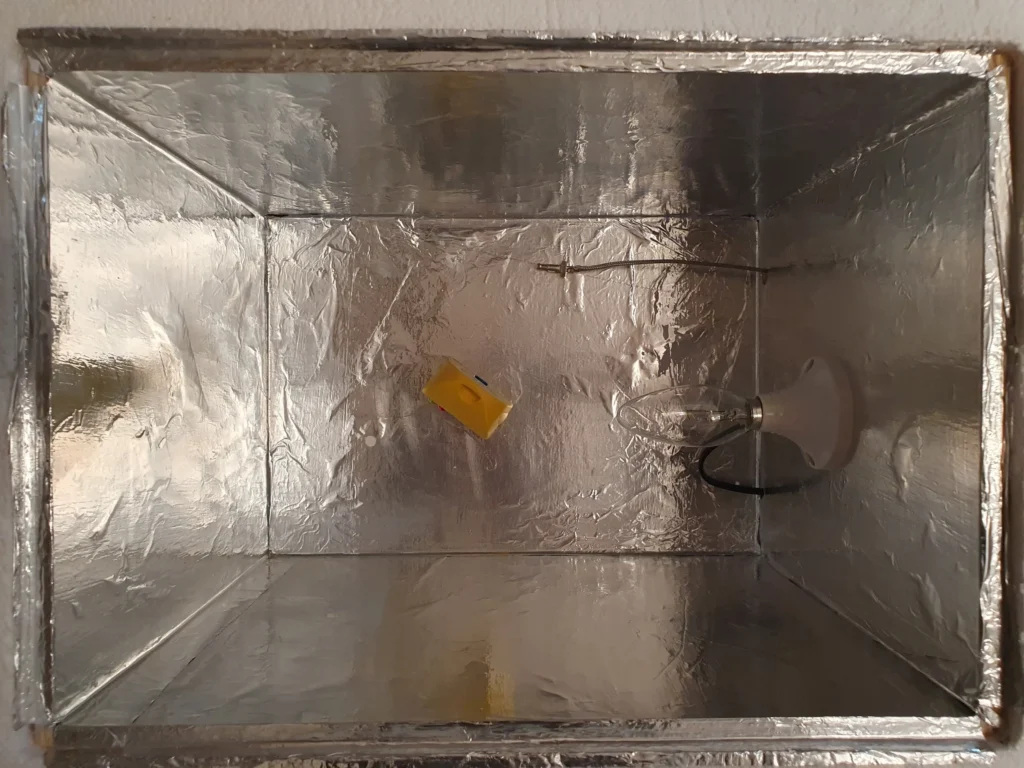
This type of box has the advantage of being easily modified with holes and any cut-outs needed for the various cables. The internal sides of this box have been reinforced with 5mm plywood and then covered with aluminium foil as shown here:
The yellow device in the box is the datalogger. It is used during setup to check on temperature stability (see next graphs). The thermocouple is at top right with the light bulb screwed into the side.
Temperature Stability
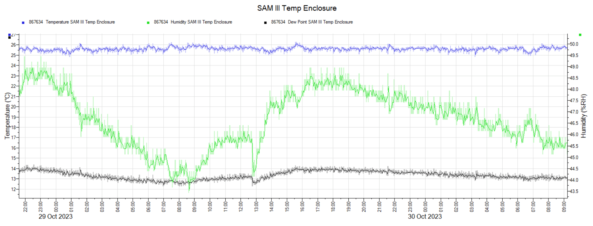
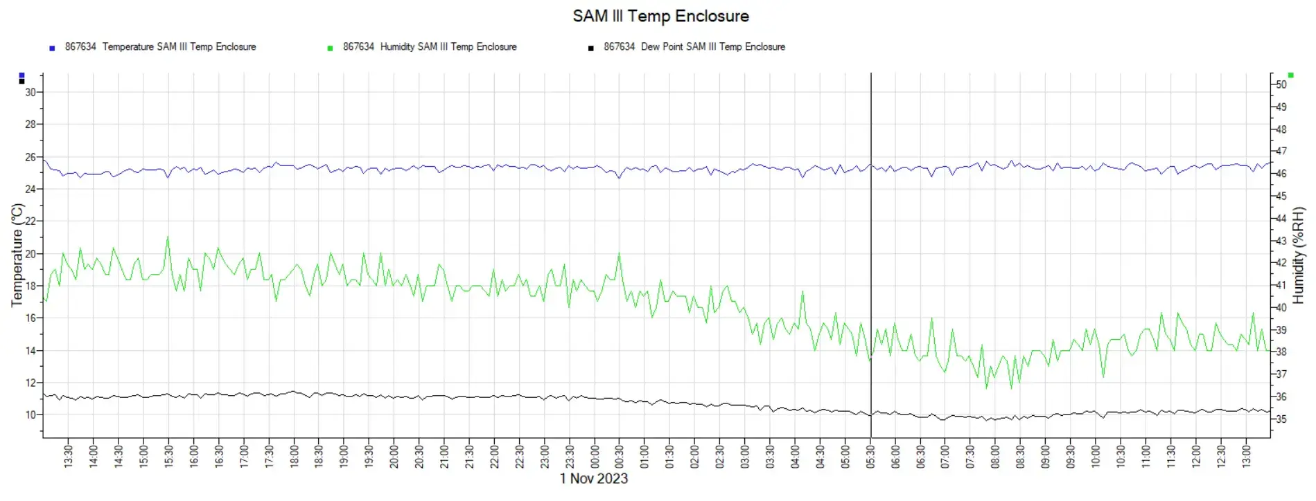
Data from the logger are shown below. Temperature profiles (blue trace) at three different timescales are shown in the following charts. Also produced are measurements of humidity (green trace) and dew point (black trace), which were recorded at the same time by the logger. They can be ignored for our purposes.
Recordings taken after every 10 seconds
Recordings taken after every minute
Recordings taken after every 5 minutes
These graphs suggest that this simple on/off control by the Arduino should be adequate for this application. It is able to control the temperature to within about ±1°C.
For more precise adjustments, full PID (Proportional, Integral, Differential) control can be considered. But for now, we shall see how well on-off control works and monitor the response from the magnetometer.
Finally, this YouTube short video presents the enclosure in action. The box lid had previously been removed to allow some air circulation and change in temperature. This explains why the lamp heater is switching on and off quite frequently in the video. Once at a stable set point temperature, this on/off switching is much less frequent.
Final Words...
For now, the enclosure can be considered finished. As mentioned in the Introduction, a LC display can be added in future by connecting a 1602 LCD display with an I2C adapter, as explained in Part I of this project.
The box is now ready to receive a 3-axis fluxgate magnetometer. Much more about that in a future post…
6 Minute ReadIntroduction Magnetometers are instruments used to measure magnetic fields. They have been around in different forms since the great physicist and mathematician Karl…